News, Updates and Other Minutiae
August 2019
Website outage - I made some hosting changes and there was a minor hiccup. Hopefully everything is now back to normal but please let me know if anything is missing.
The start of a new project added in the Homebrew category. Specifically, a Frequency Dependant Switch. Measures the incoming frequency and switches 1 of 8 outputs on. Software for this project uploaded.
June 2019
Added another project for the AD9850 DDS modules. A Simple DDS sweeper in the Homebrew section. This is an absolutely basic, no frills project using a 12F1840 to sweep a DDS module between a range of frequencies. Plenty of scope for you to improve on the software and add extra features.
Privacy Policy uploaded. It may be viewed at the Privacy Policy link in the footer.
Custom code/webhost costs
I have, for quite a while, provided modified versions of the code for my projects free of charge. However, the cost of webhosting for this site has tripled in the last few of years and shows no signs of getting any cheaper.
As of October 2017, I will be asking for a donation in exchange for providing custom modified code for my projects to help keep this site available.
GPDR and all that stuff
In accordance with various bits of legislation around the world, either currently in force, about to come into force or proposed, you will now find that annoying "We use cookies" notice at the top of this website. Please note that the ONLY cookies currently used on this site are for that pop-up (see https://cookieconsent.insites.com/) and Google Analytics. The full Privacy Policy is available at the Privacy Policy link in the footer at the bottom of the page. (If you don't know what GPDR is, Google it. Real scary shit for ANYBODY with a web presence.)
VK5TM Noise Canceller
November 2019 - Kits & pcb's still available. A PCB is available for this project for $10 (Australian residents $11) + postage and packaging. A kit of parts, excluding knobs, connectors and case, is also available. Please note that I currently pack in batches of 10 kits at a time, so depending on order volumes, there may be a slight delay as I await some parts to be restocked. Price is $50 ($55 in Australia) + postage and packaging. An assembly service is also available for the kit for an extra $30 ($33 Australia - the extra is the GST). This is for the kit only, no knobs, connectors or case is provided. All prices in Australian dollars. Payment via Paypal, details will be advised at time of order. Use the Contact form to order. Kit pricing is subject to currency rate fluctuations and postage is subject to change at the whim of the postal service. Note to UK purchasers - Amateur Radio equipment and electronic kits can be imported with 0% duty under the commodity code 8525600000 (current as of Sep 2017). You will still have to pay VAT at the current ruling rate.
ERRATA - In the SPRAT magazine article, there is a cap (C16) missing from the circuit diagram. The circuit diagram on this page is up to date.
***LF/MF Mod - see bottom of page*** The original version of the Noise Canceller, as far as I can tell, was developed about 1989 by G4WMX and GW3DIX. A similar device was also available commercially from SEM as the QRM Eliminator. Later, Hans DK9NL updated it to include a HF Vox circuit. Klaus DG0KW made further refinements and it was published in Funkamateur in 2013. The VK5TM Noise Canceller is another version of the design, with the HF Vox circuit removed (it proved unreliable on SSB transmission) and a couple of other minor changes, including the use of SMD JFETs and a double-sided pcb. The operation of the circuit involves the cancellation of local interfering signals, that are picked up on a relatively inefficient 'noise antenna' and are made 180 degrees out of phase with the signal on the main antenna, which also contains the interfering signal plus the wanted signal. After the mixing of the two interfering signals, the main wanted signal remains. Tony G4WIF's blog at http://www.fishpool.org.uk/noisecancel.htm has a nice list of links (supplied by Nick G8INE) to further information. It should be pointed out that this circuit is not a cure for broadband, multiple noise sources. If you are experiencing this sort of interference, you should probably be looking more towards DSP noise cancelling techniques. Several points should be noted:- Without power applied the circuit is in bypass mode (so you shouldn't do any damage transmitting into an unpowered unit), but transmitting into a powered unit without the PTT connected will damage the electronics. Maximum transmit power through this unit should be 100w or less. The changeover relays are two 6V 3A contact rated units wired in series. A 220uF capacitor in series with the supply enables quick operation of the relays, while the paralleled 150 Ohm resistor reduces the hold current once the capacitor has charged. The bandwidth of the unit is determined by transformer T1, depending on the core used and number of windings. This is an area you can experiment with. There is nothing out of the ordinary as regards the circuit and construction is straight forward.
Schematic
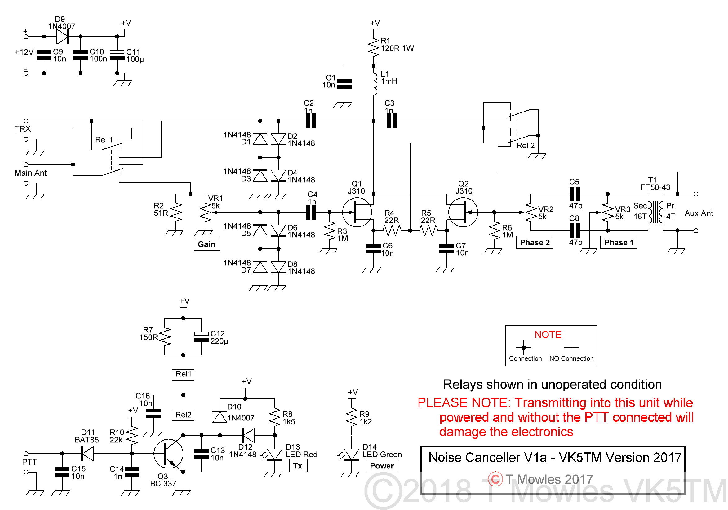
(Click picture for larger view. Click again to close.)
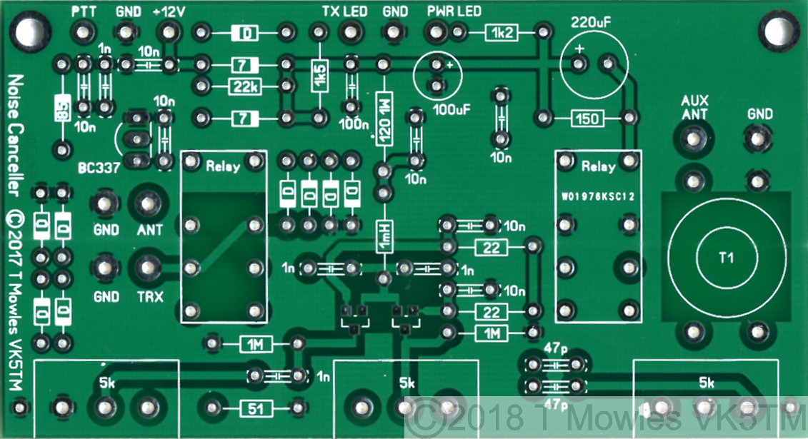
Construction
Please note that this is not a step-by-step, hold your hand construction guide, but any competent homebrewer should have no trouble building this project. This page will also be the reference (along with the downloadable pdf below) for the kit.
If you are building this for use with a receiver only, check the section further below - "Receive only option" - as some components do not need to be fitted.
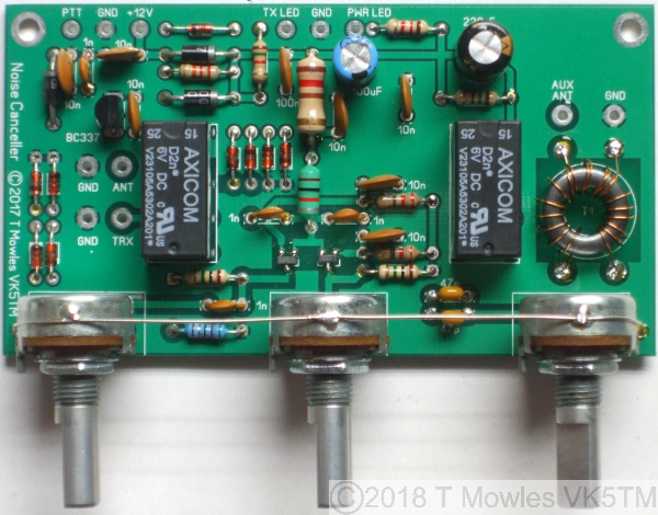
(Click picture for larger view. Click again to close.)
The diodes marked "D" are 1N4148's, "7" - 1N4007's and "85" - BAT85. (1N4007's were used as that is a standard component in my workshop, 1N4001's, 1N4002's etc should be equally suitable and a 1N5819 was used for the BAT85). The suggested sequence of construction is to first fit R1, R3 & R6 followed by L1, C1, C6, & C7. Note that R1 & L1 will run warm and should be fitted proud of the pcb by a couple of millimeters to allow airflow around them. These components are fitted first to help prevent static build-up during soldering of Q1 & Q2.
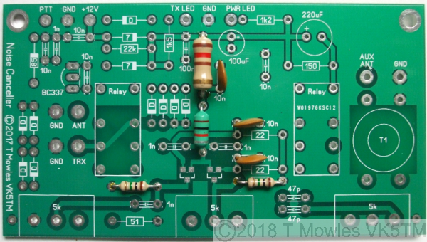
Next fit the two smd devices, Q1 & Q2. After that, fit all the remaining low profile components (resistors & diodes) followed by the remaining transistor and capacitors.
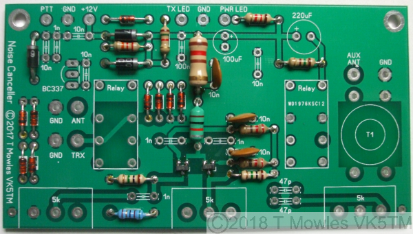
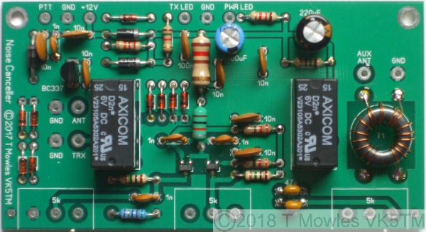
(There was supposed to be another photo here but I managed to get it out of focus, so just pretend there is one here with all the rest of the capacitors and remaining transistor fitted). Relays 1 & 2 can be fitted next followed by transformer T1, see below for receive only option. T1 is 16 turns secondary/4 turns primary, 0.3-0.4mm enamelled copper wire, wound on an FT50-43 toroid core (0.5mm wire was used in the prototype and is supplied in the kit, it is somewhat easier to handle).
Winding the toroid Me and my fat fingers are not the best at winding toroids, but here is one way of doing it and making sure the primary winding is centered on the secondary winding. You will probably have your own favourite method, including throwing it out the window when it gets really annoying. For the secondary you will need approximately 350mm of wire and 130mm of wire for the primary. Fold each piece in half.
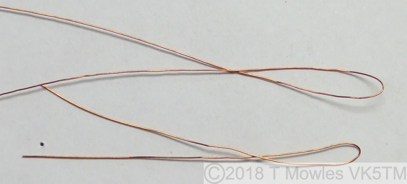
Then, keeping the wires together, twist them together. Don't worry about how many "turns to the inch" or whatever, it's only a short length and wont make a great deal of difference.
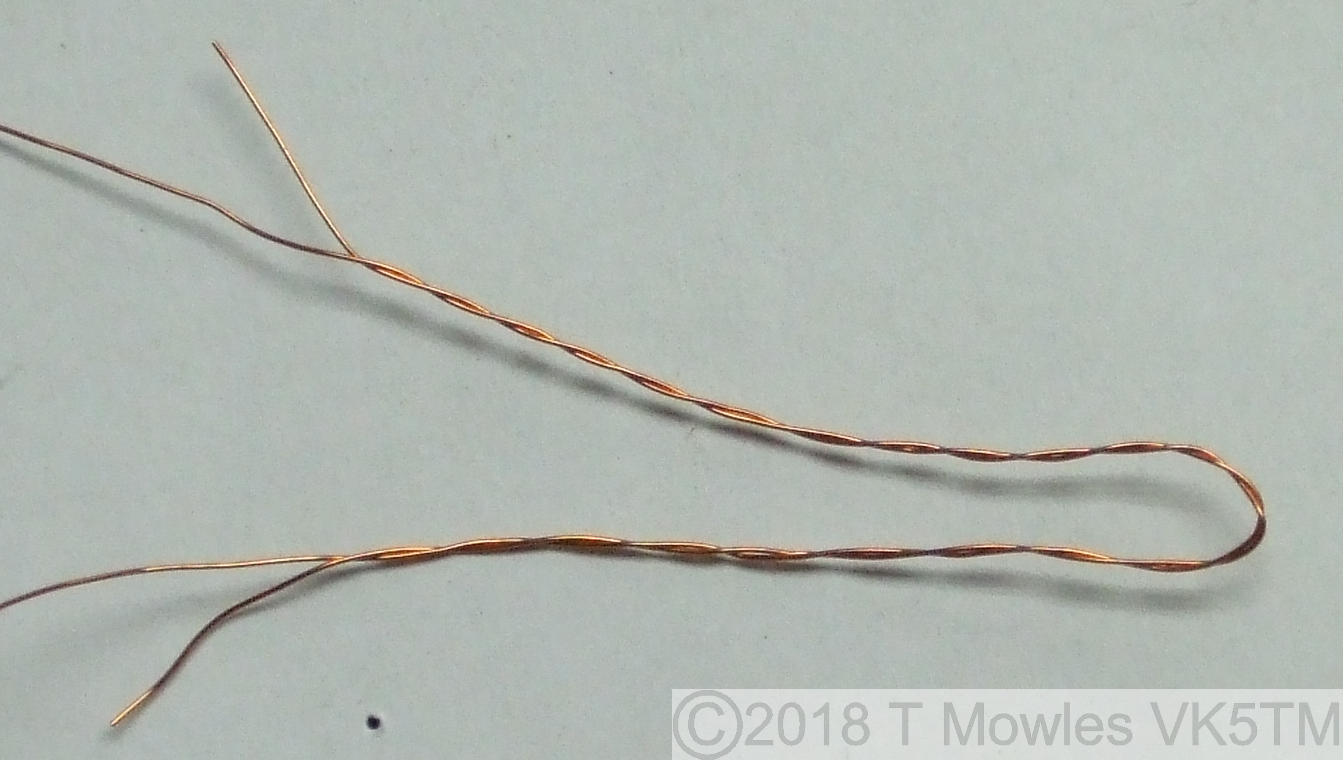
Now place the wire so one leg goes through the central hole and wind 4 turns symmetrically from that point (remember - once through the hole = 1 turn). Unwind the remaing length of the short wire from the longer length.
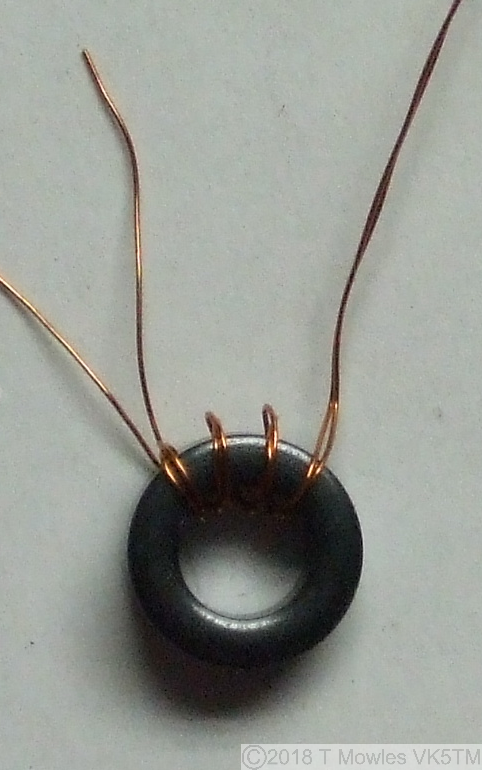
All that remains is to curse your not so nimble fingers and wind the remaining wire onto the toroid for a total of 16 turns.
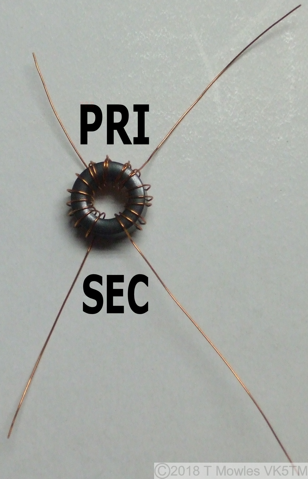
If you are going to use this unit "portable", ie out in the field, I would strongly recommend securing the toroid to the pcb. Either by gluing it down or drilling a hole in the center and using a nylon (or similar) nut, bolt, washer combination - DO NOT USE A METAL NUT, BOLT OR WASHER. Construction continued... Finally, fit the three potentiometers. An earth wire is then soldered from the earth point on one side of the potentiometers, across the top of the potentiometers to the earth point at the other side. This wire is then soldered to the body of each of the potentiometers.
Hand capacitance has a marked effect on the controls, particularly VR2 (Phase 2), as does stray external RF, so this unit should be mounted in a metal enclosure. If you have or can source potentiometers with plastic shafts, they would be better than the metal shaft variety, non-metallic knobs should also be used. Once assembled, double check that all components are correctly oriented.
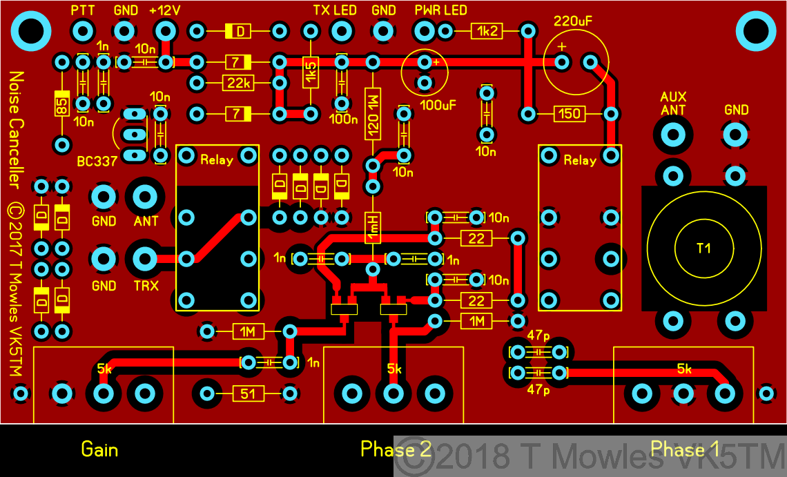
Receive only option
If you are building this to use with a Receiver only, you can leave the relays off. You will need to add 3 links in place of the relays as in the overlay below. Additionally, all the components with a cross over them need not be fitted. They are for the PTT/relay control function. Please make sure you mark somewhere on it that this is for receive only. Transmitting into it will destroy it.
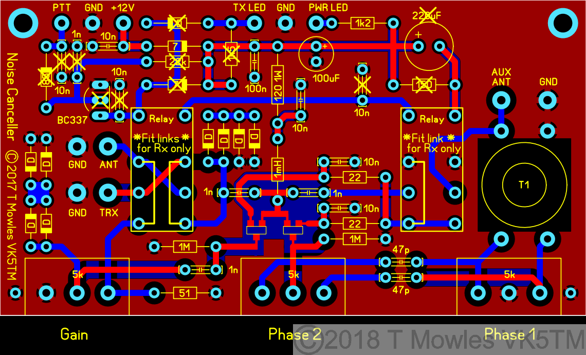
(Click picture for larger view. Click again to close.)
Component substitutes
Diodes have already been mentioned above, which really only leaves the JFETS, BC337 and relays. Firstly the JFETS. If you do decide to substitute something else, MAKE SURE the Drain and Source connections are interchangeable. Not all JFETS are. A 2N3904 can be used in place of the BC337, but you will need to reduce the value of the 22k Base pullup resistor to 6.8k and the transistor is fitted the opposite way round to the BC337. Experiment with this resistor value if you use a different transistor to get reliable switching of the relays (and double check the transistor leadout). Relays. Those specified in the parts list have 3A rated contacts and 6v coils. Relays with 5v coils will work without any changes. 1A rated contacts will be getting close to the margin at 100W Tx power (100w in 50 ohms is 1.4A), even though the Tx/Rx relay contacts are paralleled in Tx mode (if you are or will only run QRP levels, 1A contact rating should be fine). Also make sure the coil pins are not polarised on any substitutes.
Testing
This first phase is done without connecting the Noise Canceller to anything other than a power supply in the first two steps. 1. Connect a 12-15v power supply (the circuit is diode protected against reverse polarity) and all being well, the power Led should light and the relays click in. If not, disconnect the power and rectify any problems. The current draw at 13.8V, with the relays specified, should be between 90 - 95 mA when the relays are activated and 18 - 20 mA when not activated. 2. If all is OK (and nothing let out the magic smoke), connect the point marked 'PTT' on the pcb to ground and the relays should release and the TX Led come on (note that without power applied, this circuit is automatically in Tx mode). Remove the power. 3. You will need to check with the user manual of your transceiver to see if the PTT output pulls to ground when transmitting. If not, you will need to sort something to make it so, before continuing. Connect a dummy load to the transceiver (you do have one, don't you?), else connect your station antenna and reduce power on the transceiver to as low as possible. Connect the 'PTT' line from your transceiver to the point marked 'PTT' on the pcb, you will also need to connect GND of the Noise Canceller to GND of the transceiver. Do not make any other connections to the Noise Canceller. Apply power to the Noise Canceller and turn on your transceiver. Push the PTT button and the relays should dropout and the Tx LED should come on. If all is well, you can turn off both units and proceed to the next steps, otherwise, locate and fix any problems. Second phase of testing.
PLEASE NOTE:- Transmitting into this unit while powered and without the PTT connected and working WILL damage the electronics..
There's two ways to test the rest of the circuit for correct operation, depending on whether you have a 'noise antenna' available yet or not (more about the 'noise antenna' further along). Option 1 - No noise antenna available yet. Connect the Noise Canceller 'TRX' connection to the Ant connection of your Transceiver or Receiver (yes, this unit will work on just a Receiver) and connect the PTT line. Then connect your external antenna to BOTH the 'ANT' and 'AUX ANT' connections (at the same time) of the Noise Canceller. Do not power up the Noise Canceller yet. Turn on your transceiver and make sure you can still hear signals. Set all the controls of the Noise Canceller to their mid positions and apply power to the Noise Canceller. Tune in a signal and then adjust all of the controls of the Noise Canceller, starting with the Phase 1 control, for a reduction in the signal. All the controls interact and the null can be quite sharp, but you should be able to remove most, if not all, of the received signal. Option 2 - With a noise antenna. OK, basically exactly as in option 1, but connect your main antenna to the 'ANT' connection of the Noise Canceller and your noise antenna to the 'AUX ANT' connection. You will also be looking to cancel any QRM as opposed to a wanted received signal. If you have an ATU connected to your main antenna, connect the Noise Canceller between the transceiver and ATU and use as normal.
Final Assembly
Once you have completed testing, assemble the Noise Canceller into a metal enclosure, using which ever connectors match what you use in your station for the antenna/rig connections. The connectors for 'PTT' and power can be anything suitable for the purpose. Reasonable quality RG58 should be used to connect to the RF connectors and it might be an idea to twist together the pairs of wires from the power and PTT connectors and LED's to the pcb.
Noise Antenna
Because everybodies situation is different, it is not possible to say 'you need x type of antenna' in relation to a noise antenna, so these are just some general comments. Some may get away with just a few turns of wire wrapped around a ferrite rod or a short whip antenna, for others, several feet of wire strung up between two points may be needed. The one thing you don't want is an efficient antenna as a noise antenna. You need to pick up more of the noise as opposed to the wanted signal, so you will also need to keep the noise antenna away from your main antenna. Positioning of the noise antenna depends entirely on your own individual situation, so some experimentation as to placement may be needed for the best results, e.g. if you know the QRM is coming from your neighbours plasma tv, place the noise antenna as close as you can to that side. A noise antenna does not need to be 'matched' or 'tuned' to the 'AUX ANT' input.
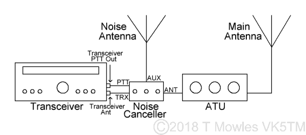
Connecting Up
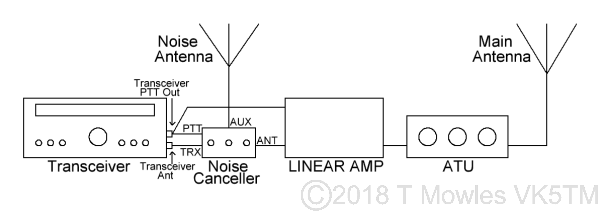
Although you have already made the connections in the testing phase, below are a couple of diagrams to make it clearer if necessary. If you have a Linear Amp, the Noise Canceller goes between the rig and Linear as below.
LF/MF Mod
I had an email from Max IK0VVE to let me know that he has this Noise Canceller working down at 2200m (136kHz). He replaced the FT50-43 with a BN73-202. The number of turns used by Max is 8 & 2. Don't forget that when winding binocular cores, 1 turn is through the hole on one side and back down the hole on the other side. The following PDF file, hosted here by kind permission of Jim Kortge K8IQY and the 4SQRP Group, shows how to wind a binocular core. ***Winding turns and core type details in the PDF are not for the Noise Canceller transformer - see above*** Right click and "Save as" or whatever is required by your browser Winding a binocular transformer.
Downloads
Because of copyright infringements of my pcb designs by others who should know better, I will not be posting the PCB files for this project. I'm not talking about those who have made one or two for themselves and a friend, but those that have blatantly made and sold copies of my pcbs for profit without my permission. Parts list as PDF The parts list for the Noise Canceller. This page as PDF A modified version of this webpage in PDF format. Updated March 2019.
Acknowledgement
I would like to thank Tony G4WIF, Nick G8INE and Paul VK4APN for their valuable feedback during construction of the original (single-sided) prototype version of the Noise Canceller.
Also, check out the 4SQRP website and their range of kits:- 4SQRP website.