News, Updates and Other Minutiae
August 2019
Website outage - I made some hosting changes and there was a minor hiccup. Hopefully everything is now back to normal but please let me know if anything is missing.
The start of a new project added in the Homebrew category. Specifically, a Frequency Dependant Switch. Measures the incoming frequency and switches 1 of 8 outputs on. Software for this project uploaded.
June 2019
Added another project for the AD9850 DDS modules. A Simple DDS sweeper in the Homebrew section. This is an absolutely basic, no frills project using a 12F1840 to sweep a DDS module between a range of frequencies. Plenty of scope for you to improve on the software and add extra features.
Privacy Policy uploaded. It may be viewed at the Privacy Policy link in the footer.
Custom code/webhost costs
I have, for quite a while, provided modified versions of the code for my projects free of charge. However, the cost of webhosting for this site has tripled in the last few of years and shows no signs of getting any cheaper.
As of October 2017, I will be asking for a donation in exchange for providing custom modified code for my projects to help keep this site available.
GPDR and all that stuff
In accordance with various bits of legislation around the world, either currently in force, about to come into force or proposed, you will now find that annoying "We use cookies" notice at the top of this website. Please note that the ONLY cookies currently used on this site are for that pop-up (see https://cookieconsent.insites.com/) and Google Analytics. The full Privacy Policy is available at the Privacy Policy link in the footer at the bottom of the page. (If you don't know what GPDR is, Google it. Real scary shit for ANYBODY with a web presence.)
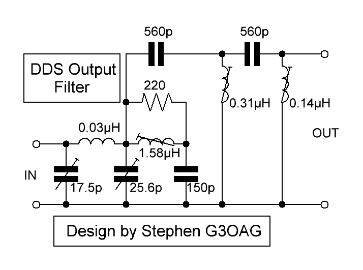
This is a filter/leveller for use after an AD9850 DDS module, from G3OAG. I will let him explain the circuit in his own words (edited and condensed from our email conversations).
G3OAG DDS Filter/Leveller
I have worked out that levelling the DDS output can be achieved with a simple high pass filter. My DDS, using an e-Bay module and 2N3904 amp stage, gives me 10.3dbm at 10.8Mhz (1.8Mhz + 9Mhz offset) down to 2.3dbm at 38Mhz (29Mhz + 9Mhz )...a difference of around 7.5dbm. Up to now, using a simple T design, three pole high pass filter, I have achieved some degree of levelling with 2 x 470pf caps in series and a coil of around 0.1uh in the middle. This obviously lets the higher frequencies pass relatively unattenuated, and the lower frequencies are attenuated so that at the output of the filter, the level is getting on to the same level as the higher frequencies. After further experimentation, I have ended up with ten components after trying three previously. You can see the output of the final 2N5109 amplifier and splitter for the two DBM's is within 1db across the nine bands. I do not think this circuit is totally repeatable, as there will be various capacitance and inductive differences between different builds. I ended up having to use a damped trap ...the 1.58uH coil and the 150pf with the 220 ohm, to lower the 160m output which as you know is very high compared to the 10m output - in this case a range from 10.8Mhz to 38Mhz owing to the 9Mhz IF offset. However, it seems to function OK, and I'm sure other builders can make the necessary changes.
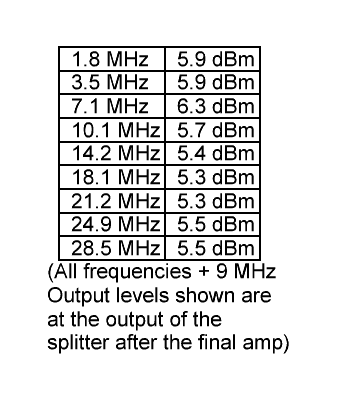
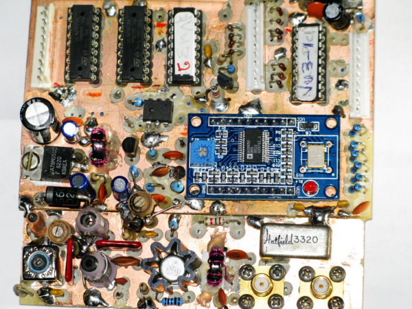
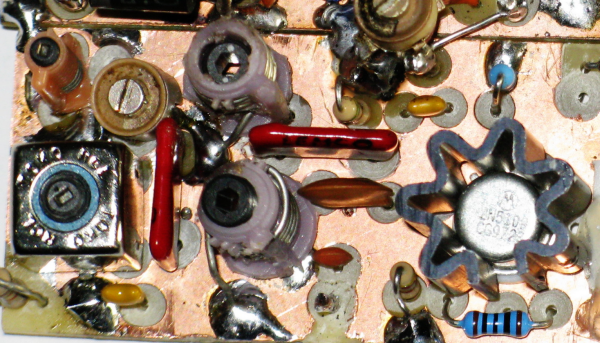
The amp following the e-Bay DDS board which uses a 2N3904, is from the LU5DJV DDS circuit, but they are all similar. This outputs around 10.5dbm at 160m (10.8MHz with the 9Mhz offset) going down to around 2.3dbm at the 10m band...38Mhz. The amplifier following my filter is the standard 2N5109 Class A design, originally in the ARRL Handbook, which has been used everywhere, and gives around +17db to +20db gain. This feeds a power splitter, which gives two equal outputs to feed both the receive and transmit mixers. I was hoping to get the magic +7dbm out from each output, but owing to losses in the filter, I am getting around 5.5dbm...not that it will make much difference. Below are two photos of my DDS and the filter, which is crammed onto the board. The two chips at the top left are 2x ULN2803A which are the drivers for the band relays in the RX input filters and the PA output filters, and also for the mode switching. You can also see at the bottom right the ancient Hatfield 3320 splitter and the two SMA sockets which feed the RX and TX mixers. This is the VU2CNS DDS circuit which works well. This DDS will go into my homebrew 20w rig which I built years ago and which currently uses a Vackar VFO and which I've had hundreds of QSO's with. My new build DDS will go into a new rig.